Every hobby servo ships with the same assumption baked into every tutorial: pick a minimum pulse, a maximum pulse, draw a straight line between them. It’s quietly wrong — the real pulse-to-angle curve bows away from that line, sometimes by several degrees. Servo Calibrator is the tool that measures your own servo’s real curve instead of assuming one.
Wire up any Arduino with I²C and a PWM-capable pin, an AS5600 magnetic encoder, and the servo you want to characterize; open one self-contained HTML page in the browser; click Calibrate. The firmware stall-scans both directions to find the servo’s true mechanical limits, sweeps the full range twice, and builds a direction-averaged 20-point lookup table — no protractor, no hand measurement, usually done in under a minute. Once calibrated, the same page drives and plots a live trajectory against that table, with a toggle to compare it against the naive 2-point line in real time.
This tool is purely for characterization — it doesn’t ask about horn position, direction, or a logical zero point, and it always reports the servo’s own physical range, [0, maxAngle]. Turning that into an actual motor-driver constructor for your project is a separate, application-specific step.
Wiring
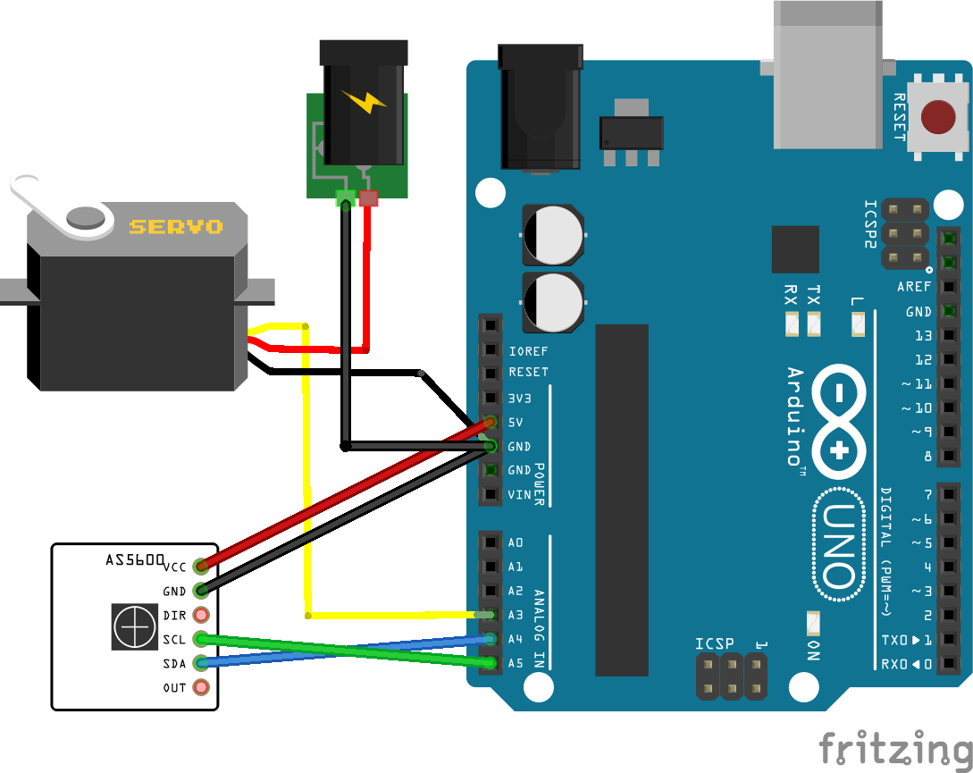
The AS5600 never touches the servo — it’s a contactless magnetic angle sensor that just watches a magnet spin underneath it. That means the one physical requirement is a diametrically magnetized magnet (poles across the diameter, not the faces) mounted on the servo’s output shaft, centered over the chip, a millimeter or two above the package. I didn’t build any special mount for mine — just glued the magnet onto a spare servo horn and bolted the horn back on.
Everything else is ordinary wiring: servo signal to a digital pin (A3 in the stock firmware), AS5600 on the board’s I²C bus (SDA/SCL — A4/A5 on an Uno/Nano), common ground tying the Arduino, the AS5600, and the servo together.
The one thing worth getting right is power. Run the servo off its own external 4.8–6V supply, not the Arduino’s 5V or Vin pin — a small board’s onboard regulator generally can’t source a servo’s stall current. 4.8–6V covers most hobby servos, but check your particular servo’s datasheet before wiring it up; some digital servos want a narrower or higher range. Either way, tie that supply’s ground to the Arduino’s ground, or both the encoder readings and the servo’s behavior get unreliable.
Getting the firmware to compile
The sketch needs four libraries that don’t ship with the Arduino IDE — one third-party, three of mine — so a fresh install needs a few extra steps before ServoCalibrator_Companion.ino will build:
-
Install AS5600 (RobTillaart’s) — it’s in the Library Manager’s index, so
Sketch → Include Library → Manage Libraries…, searchAS5600, install the one by RobTillaart. Or from the command line:arduino-cli lib install "AS5600". The firmware talks to it through Universal-Encoder-Interface rather than directly, but that’s a wrapper around this library, not a replacement for it. -
Add Universal-Encoder-Interface as a library — same two options as the next step. It provides
AS5600EncoderDriver, which handles reading the encoder across full revolutions without the angle wrapping back to zero every turn. -
Add Universal-Trajectory-Interface as a library — this is the step that trips people up, since it isn’t in Library Manager’s index. Either:
- Download the Universal-Trajectory-Interface repo as a ZIP (
Code → Download ZIP) and useSketch → Include Library → Add .ZIP Library…, pointing at that ZIP — the IDE unpacks it into your sketchbook’slibraries/folder itself; or git cloneit straight into your sketchbook’slibraries/folder, e.g.~/Documents/Arduino/libraries/Universal-Trajectory-Interface— no rename needed, it already ships a properlibrary.properties.
- Download the Universal-Trajectory-Interface repo as a ZIP (
-
Add Universal-Device-Interface as a library too — same two options, same place. The sketch never includes anything from it directly; it’s the shared base the two libraries above are both built on, and the IDE compiles every source file in a library whether your sketch uses it or not. Skip this and the build stops at
fatal error: IDevice.h: No such file or directory, which is confusing precisely because nothing you wrote asked for that file.Restart the IDE afterward if it was already open, so it picks up the new libraries.
-
Flash the firmware. Open
ServoCalibrator_Companion/ServoCalibrator_Companion.inofrom the GitHub repo in the Arduino IDE and upload it to your board, same as any other sketch. Servo signal is fixed at pinA3in the sketch (editSERVO_PINif you need a different one).
All four libraries are free and public — no private access or account needed for any of them.
Using the tool
Once the firmware’s flashed and the board’s wired up per the diagram above, click Launch Servo Calibrator below, then Connect… and pick your board’s serial port. Click Calibrate — one button, fully automated — and the trajectory/chart interface unlocks once the sweep finishes.
Full protocol reference, safety notes, and known limitations are in the project README.
Comments
Name and comment are public. Email is never shown or shared — it's only used if I need to follow up. New comments are held for review before they appear.
Loading comments…